Have firefox? Subscribe!

Did you know that if you are using Firefox you can subscribe to this blog and have posts listed in a bar at the top of your browser? I think it works with other browsers too! Click here to subscribe.

Saturday, November 3, 2012

Routing a tele ferrule block.


  I've been busy with all sorts of things lately, both in and out of the shop, so I haven't really had much time to blog.   I had a long weekend, so I was able to get some yardwork done, do a repair job for a co-worker of mine, and even start on a little of the actual construction of the Selmer copy.  As you can see, the shop is all sorts of messy and I wish I had more room, but I will some day when I'm actually able to do something about that.
  A co-worker of mine had heard that I went to school for guitar repair and asked me if I could route a ferrule block(click here if you're wondering what that is) for a tele copy he had.  Apparently whoever installed the previous ferrules didn't line them up or use proper drilling techniques to prevent chipping of the finish, so it was looking pretty ugly.
  I wasn't sure exactly how to remove the old ferrules, but did a little research and online forums suggested using a soldering iron to heat them up and then pull them out with a needle-nose plier.  This wasn't working for me and I wasn't too concerned with keeping the ferrules in tact, so I decided to try a screw extractor bit I had gotten from Sears a while back and it made extremely quick work of removing the ferrules.  I thought that was going to be the difficult part, but it turns out it was the easiest part of this job.

  Next, I mad a routing template for the ferrule block.  The manufacturer suggested using a half inch router bit, which I did, but I'm wishing I would have just used a quarter inch bit because the template was only a half inch wide itself, requiring me to do some fine tuning of the template to get the router bit to fit perfectly.  Then I taped the body up, marked a centerline as accurately as was possible, and positioned the template accordingly.  After I did the rout, it turned out I had positioned it slightly forward of the center of the existing string holes, so I did a little counter-sinking of the existing holes to help guide the stings from the ferrule block into the body holes that lead up to the bridge.
   I didn't take any pictures of of the routing because I was test fitting the ferrule block along the way and once it was in, it wasn't coming out easily again.  Here is the finished project and a much better looking backside of this tele copy:
    That's all I have for now, but I will be writing another post on the selmer progress soon.

Friday, November 2, 2012

A little side project for some friends, AKA cornhole!

   A while back, a couple friends of mine brought up the idea of making some beanbag toss games for a good time at parties and whatnot.  I assumed it would be a super easy project, so I offered to help them make the boards.  I soon found out that the name of the game is cornhole and I soon found some cornhole board plans up to official cornhole specs here: http://www.cornhole.com/freeguideredirect.htm

   I started with a 4'x4' piece of 3/4" plywood and ripped it in half to 2'x4' pieces.  The holes are specified to be centered 9" from the top edge and 6" in diameter.  I thought I could just chuck the fly cutter into the drill press and slowly but easily cut my holes.  It turns out the drill press only has about a 7 or 8 inch throat depth, so that idea is out and I decided that instead of investing at least about $50 on a decent hole saw, I would go the more hazardous route and chuck the fly cutter in a hand drill.  


   This was not the greatest idea, but after a couple drill battery chargings and completely dulling the cutter, I had some pretty decent 6" holes.  A little sandpaper smoothing and the holes were pretty much perfect.  It took a couple hours, but these were exactly the holes I was end up with:


   With the holes done, the next step was to run some 2x4s through the jointer for the edges of the boards.  I was going to pockethole the 2x4s, but couldn't find my jig, so I just cut the 2x4s to length and glued them to the boards.


   Next, I took a roundover bit to the assemblies to smooth out the edges as well as round over the edges of the holes.
    The last step was to cut out some legs.  I cut the angle and pivot point of one leg and used it as a template to route the other 3 legs exactly the same shape and size.  Then, the legs were attached with 3/8" carriage bolts and some wingnuts.  I had a little hardware fiasco when I decided to use the recommended locknuts instead of wingnuts.  The locknuts were impossible to remove from the carriage bolts once they were on, so I had to break out the dremel to cut one of the nuts off the bolt.

   I'm letting them handle the finishing, but here are a few photos of the completed regulation cornhole boards:


   My friend Nate even bought some bag-o-lanterns to light up the board holes for night playing, but we haven't installed those yet.


Thursday, September 27, 2012

How to make a mold

  Well, last weekend was pretty productive as well as being busy as usual.  Janice and I went to see The Heavy at the Fineline and they put on a great show as usual; I just wish it weren't at the Fineline as it's a little difficult to move around in the place.  After nursing my hangover away the morning after, I got some solid work on my mold done.
  It took a little work to smooth out the masonite full body template to my standards of matching the plan.  When I initially started making the template, I cut too much out of the cutaway and had to build it up a little bit with some sawdust and CA.  This full body template will become the pattern for the mold and side lamination/bending forms, so perfection is crucial as it determines the shape of the final guitar.  
  When I was going to school in Red Wing, my instructor suggested using an inlay bit set, such as the one at Rockler, to make the outside mold pattern from a full body template.  I had to purchase a separate base for my Bosch Colt palm router to fit the guide bushing, and it was tricky to get it centered on the collet to achieve accurate template routing.  I believe Bosch makes a jig for this, but whether you choose the jig or just eyeballing and checking with a ruler, it is worth spending some time(or money) to get it centered properly.
  The first route done with the bushing around the collar, which offsets the pattern by about a quarter inch or so.  It is crucial in this step that the collar always be contacting the template when the spiral bit is cutting, because this piece will become the template for the first layer of the mold.
   Below, is the template for the first layer of the mold, which is routed with the bushing removed from the inlay collar, leaving a perfect inverse of the original body template.
   After the first routs are made with the collar minus bushing, the remainder of the first layer of the mold can be routed out with a top bearing flush trim bit, or first cut out with whichever sort of coping, jig, or scroll saw etc... that you wish.  I didn't want to cut through the perimeter of the first layer with a band saw, didn't have my scroll saw set up, and don't own a coping saw, so I decided to route it out.  It took some time and I had a close call almost routing into the edge, but taking semi-shallow passes with the router proved to work just fine.
   The next step is clamping the mold layer pieces together and drilling a couple of alignment holes on the outside corners of the mold pieces for dowels, which act as horizontal stabilizers for the mold pieces while they are being glued up.  The first layer of the mold is then pinned to each layer and the outline is traced on each layer to be rough cut with the bandsaw.  The layer pieces are then glued up, one by one, each one being flush routed to the first layer with a flush cutting bit.  I was excited to finally use my new router table and found a solid 1-1/2" Bosch flush trim bit with 1/2" shank at Menards.
   The process is then repeated with 2 additional layers, making a total of 4 layers at a total of around 3 inches.  I then used a compass to rough an outline approximately 2" from the inside edge of the mold and this is cut on the bandsaw.
   All that is left is to clean up the outside edge with various sanders and the like, and separate the mold into two breakaway pieces held together by two toggle clamps like the one below.
  Before making the cuts at the neckblock area and the tail, lines are marked for the cuts.  The headblock area will be cut into where the cutaway meets the neckblock, and the tailblock area will be cut to the same offset of the centerline as the neck area cut.  Before making the cuts, dowel holes will be drilled in the center of the cut lines for dowels, which will be glued into one side of each half of the mold to act as alignment keys for each half of the mold.  I just need to get some lag bolts to attach the toggle clamps and the mold will be good to go.
  I'll leave you with a photo of my dust collection remotes.  Between the remote for the dust collector and having a blast gate on each power tool, operating power tools indoors has become an enjoyable task that I don't have to worry too much about cleaning up after.

Sunday, September 9, 2012

Lights and boring things like that.

  This blog is going to be short because I really don't have anything too exciting for you.  This is more of a public service announcement than anything.  The idea here really is that you need to be able to clearly see what you're working on.  If it's too dark or the lighting is too harsh, it's difficult to work, especially if you have a lazy eye and your eyes go all wonky if they can't focus properly on something.  Having adequate lighting greatly reduces that from happening. 
  After deciding that I needed better lighting, I hastily decided that flourescents were the way to go, so I bought some 4 foot 32 watt fluorescent fixtures and some little screw in light socket adapters to convert the light socket into a power outlet.  The only problem was that the adapters weren't grounded and the fluorescent ballasts require a 3 prong grounded plug.  I went back to the drawing board and started to get frustrated, realizing that a standard power outlet will not fit in the 3 1/2" junction boxes where the previous light sockets were mounted.  I did, however find some light sockets at the home depot that had a grounded electrical outlet, so I got a couple of those and a 3 outlet tap.  I wired those in where the existing light sockets were, mounted the flourescents, and was amazed at the difference.  I can now see everything in the shop, plus the t8 fluorescents seem not quite as harsh, due to their smaller diameter than a standard fluorescent bulb.  Also, since my Jet air filter has a fairly low amperage motor, I plugged that into the same outlet as the back flourescent fixture, which completely solved the dilemma of where that was going to get its power from.
  In other news, I finished the dust collection plumbing to the router table and gave the new drum sander a bit of a workout by sanding down some mdf drill press table inserts I got from Rockler that were too thick.  I was surprised at how much of the sanding dust my el cheapo harbor freight dust collector picked up.  I also found a cool extension cord at the home depot that has electrical outlets every 8 feet, which solves the issue of having no electrical outlets on the outside wall of the shop where the router table, spindle sander, and belt/disc sander are   Template perfection and mold making will begin to happen on Thursday.  That's all I got.

Saturday, September 1, 2012

Setting up shop again...

  I've decided its time to stop bummin around and finally set up shop  and start building more guitars.  I started setting up shop, but had to move my tools yet again due to some personal business in my life.  I finally got my tools moved and have since been working on setting up a legitimate, functional workshop.

  About a year ago, I made an attempt to set up shop again, but progress was slow and financial constraints kept it so.  I found a great plan for a rock solid plywood workbench on Fine Woodworking's website at http://www.finewoodworking.com/Workshop/WorkshopArticle.aspx?id=29507 and built the workbench to the plan with a few dimension modifications to fit my space and height requirements.  It is built with a pretty simple and neat system of plywood lamination to make perfectly fitting mortise and tenon joints(see article for details).  Here are a few photos of the workbench construction:

  Glueing up the leg slats.  The plywood pieces sticking out are spacers covered in tape to leave a gap which becomes the mortise:
  In the photo below, you can see the horizontal slat with the center laminated plywood piece being longer becoming the tenon:
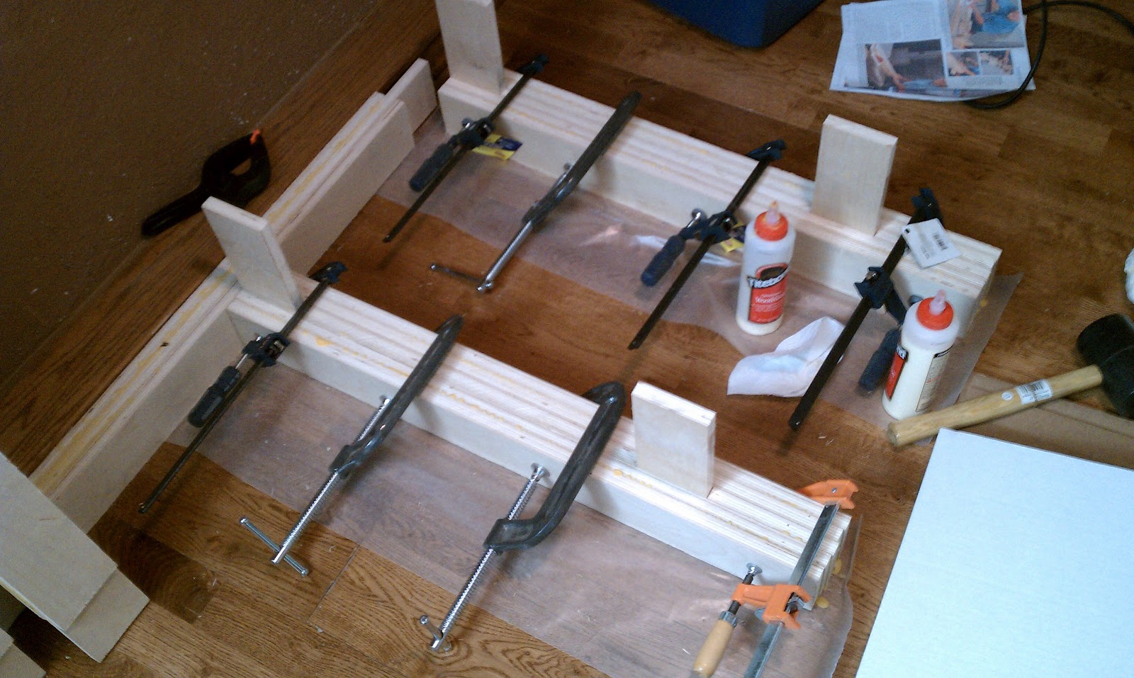
  All the pieces glued up and ready for assembly:
  The completed bench:
  My tiny shop space was originally intended to be an extra bedroom, so the closet also became a workbench space:
  At the same time that I built the workbench, I also built a router table using the same system of laminated plywood mortise and tenon joinery.  Table top is a Rockler HPL table setup.  I have a Bosch 1617EVSPK router mounted in the table and it works like a champ.  This is one solid router table:

  This years tax return was pretty decent, so I decided to blow it on a drum sander, which I will be using very shortly to thickness a guitar top and perhaps an electric body blank soon.  They had a great deal on the sander, so I was able to get the infeed/outfeed table attachments, which I have read are a must for this sander.
  With things getting serious and my shop being tiny, I decided that before I can use any of my fancy tools that I need to set up some dust collection.  I lost a few parts from my el cheapo harbor freight dust collector, so I decided to seek out replacements.  In doing so, I stumbled upon a canister conversion to improve efficiency of the dust collector as well as letting less fine dust back out into the air.  The info on these kits can be found at Wynn Environmental's website.  I also decided that, in order to save space in the shop, I would put the dust collector in the next room over, which conveniently happens to be where my  breaker box is located with a separate 20 amp circuit perfect for dedicating to the dust collector.  I picked up a dust-right through the wall port kit from rockler to make things look nice.

  Here is the dust collector with the cartridge filter and wall port:


  The next step was to also run the dust collection plumbing to my tools.  This turned out to be a bigger and more expensive task than I anticipated.  Most of the hose is 4" with 2 1/2" hose running to the drill press fence and the router table fence.  I just have a few more lines to run along the back stucco wall and my dust collection system will be complete.

  The shop side of the dust port.  I have 2 blast gates on each side of the Y to isolate each half of the shop and save on CFM since the dust collector isn't the greatest piece of machinery.  I have tested the system out and it takes care of most of the dust created by the machines:


  A while back, my little craftsman jointer was stored in a wet basement and got some nasty rust accumulation.  A couple weeks watching craigslist and I found a Grizzly G1182HW 6" jointer for $200.  Not bad, considering they are around $450 plus freight on Grizzly's website. 

   There were just 2 upgrades needed on this bad boy.  First off, the jointer only had a dust chute with no dust collection hookup, so I ordered a dust hood with a 4" port for a whopping $2.25 from Grizzly.  Secondly, the knives were pretty dull, so I decided to replace the cutterhead with a spiral cutterhead from Grizzly, which is currently on sale for $25 off.  Grizzly shipped my order out just a couple days after I ordered it, so I was able to get it in this weekend.  The new cutterhead came with new bearing blocks and a pulley attached so its just a matter of taking off the fence and cutterhead guard, loosening a few nuts, taking the old one out and dropping the new one in.
  The old cutterhead comes out...
   And the new one drops in:
  An hour or so of setting the outfeed table, squaring the fence, and getting the motor re-mounted to minimize vibration, and it's cutting quite nicely:

  In my search for a jointer, I contacted a guy on craigslist who had a bunch of Jet tools for sale.  The jointer was gone, but he did have a planer and an air filtration unit for sale, so I went to check stuff out.  The planer was pretty rusty, so I decided to pass on it, but the air filter had never been used and I was able to score it for $150.  Not bad considering these things retail for about $370.  The filter was junk, so I decided to upgrade it to a washable filter and picked one up from Rockler with a coupon for about $40.  Mounting the thing was a pain.  Not only was it heavy, but the floor joists where I was mounting it were nowhere near 16" apart so I had to mount some 2x4s to the ceiling to attach the air filter.

  Well, that is where I'm at.  I think that on Monday, I may find some new overhead lighting, because the current lighting situation is very poor.  It's pretty nice when the sunlight is coming through the window, but it's nearly impossible to work there after the sun goes down.

  Here are a few shots of the tight space I have to work in.  Luckily, most of the bigger tools have casters, so I can move things around depending on what I need to work with.  No space will be wasted.


  Several months ago, I purchased a plan from LMI for a Selmer model 807 guitar, the original Gypsy jazz machine  I also got a top, but still need to find some veneers for the back and side laminations.  I started making a full body template, which just needs a little bit of final smoothing, and it will serve as the template for making a mold and side laminating forms.  I'm hoping that I will have a finished mold for the next post.